https://habr.com/en/post/499190/- Global Positioning Systems
- Algorithms
- Mathematics
- Robotics

When it's necessary to evaluate the orientation angles of an object you may have the question — which MEMS sensor to choose. Sensors manufacturers provide a great amount of different parameters and it may be hard to understand if the sensor fit your needs.
Brief: this article is the description of the Octave/Matlab script which allows to estimate the orientation angles evaluation errors, derived from MEMS accelerometers and magnetometers measurements. The input data for the script are datasheet parameters for the sensors. Article can be useful for those who start using MEMS sensors in their devices. You can find the project on
GitHub.
We are using the following conditions:
- We're going to estimate the attitude of the stationary object.
Why?
The orientation of the moving object cannot be calculated reliably by using following formulas and you'll have to use more sophisticated algorithms.
- We will use measurements of the MEMS accelerometers and magnetometers to evaluate orientation angles.
1. A bit of theory
Orientation angles
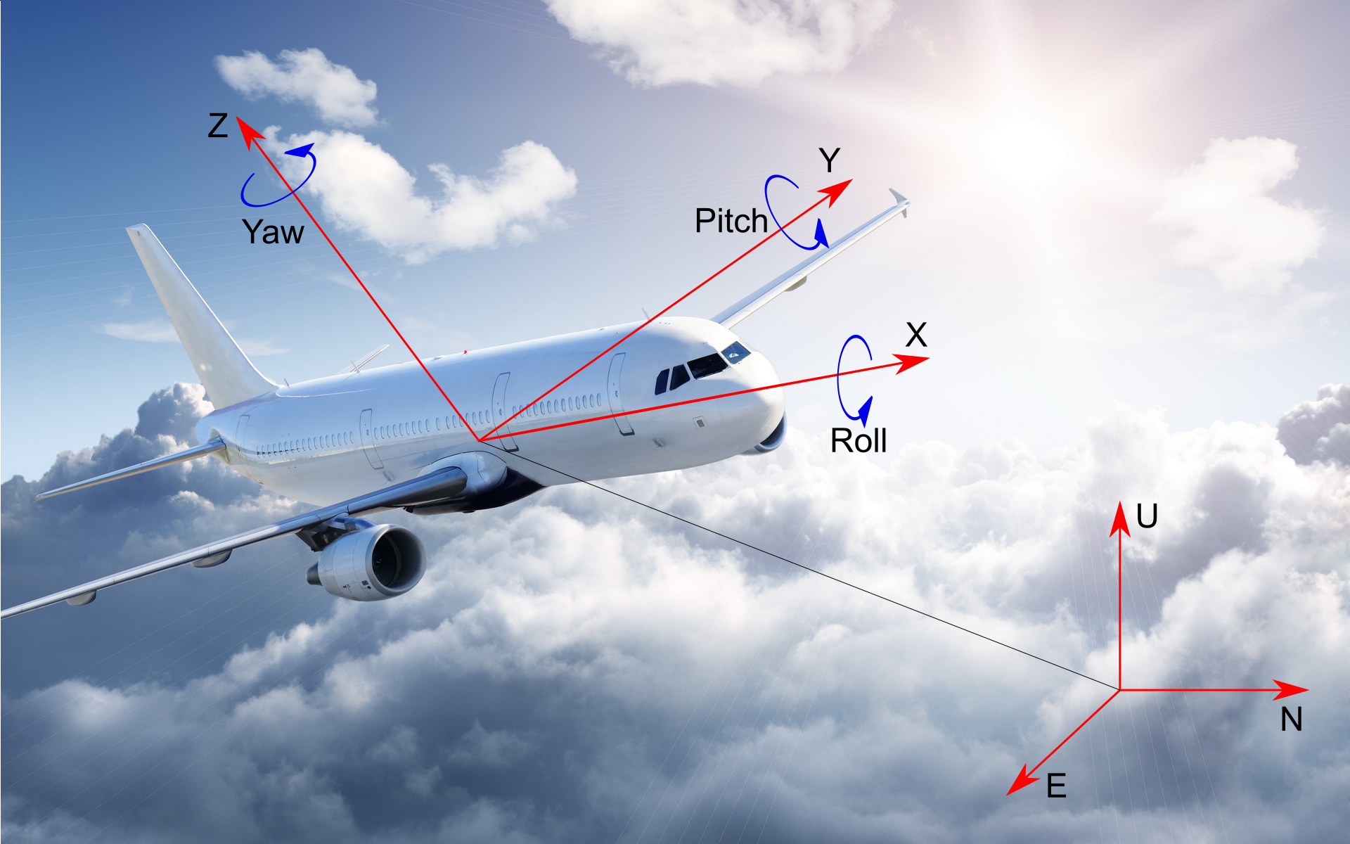
Here, orientation angles is the three Euler Angles — Roll, Pitch and Yaw. They connect the body frame coordinate system XYZ and the local coordinate system East-North-Up (ENU). The Roll, Pitch and Yaw angles denote the rotation that the XYZ axes must make in order to move in the ENU axis.
Accordingly, zero angles mean that the X axis of the object is oriented to the east, the Y axis of the object is oriented to the north, the Z axis is oriented up. The order of axes rotation is following: first Yaw (around Z axis), then Pitch (around Y axis) and then Roll (around X axis).
Accelerometer
This sensor measures the projection of proper acceleration onto the sensitivity axis. It's proper acceleration because the accelerometer measures gravity too (readings not zero even if the sensor is stationary). You can imagine the accelerometer as the weight on a spring. Its measured values are proportional to the stretching degree of the spring. If the accelerometer is stationary the spring is stretched only by gravity. If the accelerometer is in a dynamic state then there'll be a sum of forces: caused by inertia of the weight
and gravity
.
We use the following measurements model for the orthogonal (mutually perpendicular) triad of accelerometers:
where
is the measured acceleration vector in body frame coordinates XYZ,
is the matrix of axes misalignments and scale factors of the accelerometers triad,
is the true acceleration vector in body frame coordinates XYZ,
is the accelerometers zero displacement vector (biases),
is the measurements noise.
The matrix of the axes misalignment and scale factors is:
where the elements located on the main diagonal (
) are scale factors and their errors along three axes of the accelerometers and the remaining elements of the matrix are axes misalignments of the accelerometers triad.
Selecting accelerometers parameters from the datasheet
Magnetometer
The sensor that measures the projection of the magnetic field induction onto the sensitivity axis. The magnetometer is characterized by hard-iron and soft-iron distortions. Hard-iron distortion is an additive effect: a constant component is added to the measurement. For example, the reason may be the influence of a permanent magnet or a zero offset of the sensor. Soft-iron distortion is a multiplier effect: it reflects a change in direction and/ or attenuation of the magnetic induction vector. This effect can be caused by the presence of a metal object in the immediate vicinity of the magnetometer or by the sensor’s own distortions — an error in the scale factor or its axes misalignments.
We use the following measurements model for the triad of magnetometers:
where
is the magnetometers measurements in body frame coordinates XYZ,
is the diagonal matrix of the axes misalignments and scale factors (which also describes the soft–iron effect),
is the true magnetic induction vector in body frame coordinates,
is the sensors biases (also describes the hard–iron effect),
is the measurement noise.
Matrix of the axis misalignment and scale factors of the magnetometer:
elements located on the main diagonal (
) are the scale factors and their errors along the three axes of the magnetometer, the remaining elements of the matrix are axes misalignments of the magnetometers triad.
Selecting magnetometer parameters from a datasheet
Orientation angles calculation
Due to the the Earth gravity accelerometers «sense» the down direction. Their measurements are used to calculate roll and pitch angles.
Here you'll find the formulas to calculate them. The yaw angle (in this case it's the magnetic azimuth) can be determined due to the Earth’s magnetic field. The induction vector of the magnetic field is measured by magnetometers and their measurements are involved in the calculation of the yaw angle.
We should notice that to calculate the magnetic azimuth it's necessary to use the magnetometer measurements translated to the horizontal plane.
Here you'll find the formula for calculating the magnetic azimuth.
where
is the full arctangent function,
,
,
— measurements of the accelerometers along three axes in the body frame,
,
— measurements of the magnetometers along the axes X', Y' (measurements of magnetometers are translated to the horizontal plane).
2. Orientation angles estimation errors
Algorithm description

- We create an arrays of random Euler angles roll, pitch, yaw. They specify sets of the true orientation of the object in the model.
Why do we use so many angles?
Errors depend on the values of the orientation angles and if we want to get an idea of the errors magnitude over the entire range then this is the easiest way.
- Using created angles we evaluate transformation matrixes from body frame to the local coordinate system: where , , , , , .
- Using this matrix we got an expression for true accelerations in body frame coordinate system:
is the vector that determines the direction of gravity expressed in units of g, is the coordinate transformation matrix from the local coordinate system to the body frame (the inverse of the transformation matrix from the body frame to the local coordinate system).
- Accelerometers measurements model:
- Roll and pitch angles estimations calculated using the formulas:
- It's also necessary to form the conversion matrix to the «horizon» from these angles. We used rpy2mat fuction: where the roll and pitch angles are the angles calculated from the accelerometer measurements and the third angle is zero.
- Then we took the vector of true magnetic induction in the local coordinate system ENU and translated it to the body frame XYZ:
- Magnetometers measurements model:
- Then we recalculated the magnetometers measurements from the body frame to the «horizon»:
- Using the «horizontal» measurements of the magnetometers we calculated the magnetic azimuth (estimation):
- Orientation angles estimation errors calculated as the difference between the true angles of roll, pitch, yaw and calculated from the sensors measurements — roll', pitch', yaw'.
3. Results
Here is the results for two sensors which we use as an example — ADIS16488A and MPU-9250 (maximum errors).
Note that this results is not a strict verdict. Results depends on supposed calibration errors. Our script should be used to get acquainted with the orientation angles estimation errors magnitude order and dependance on different input parameters.
Accelerometers and magnetometers errors influence on the orientation angles estimation errors
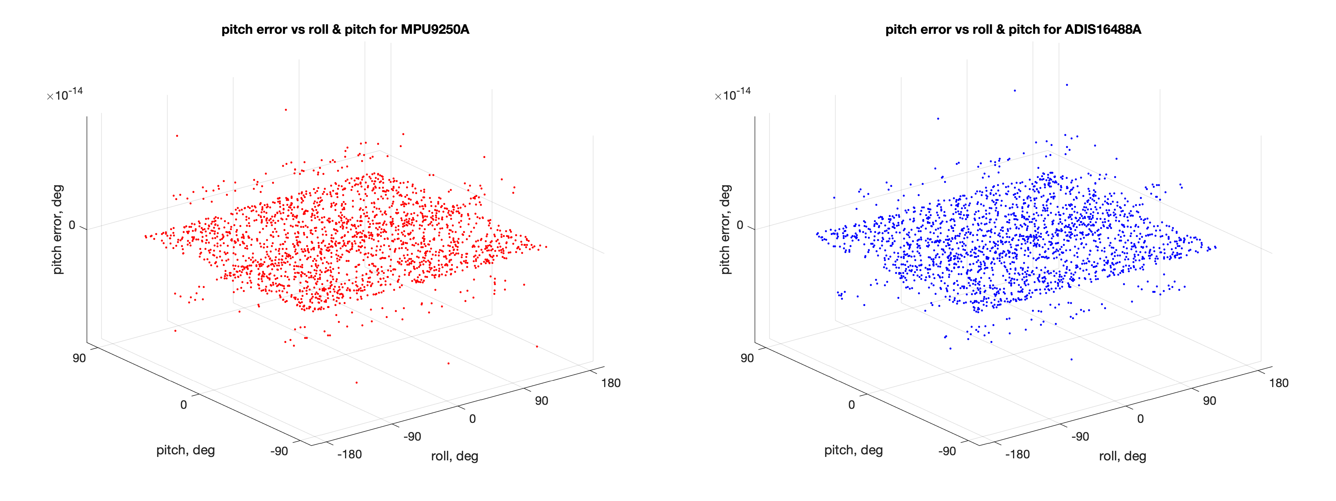
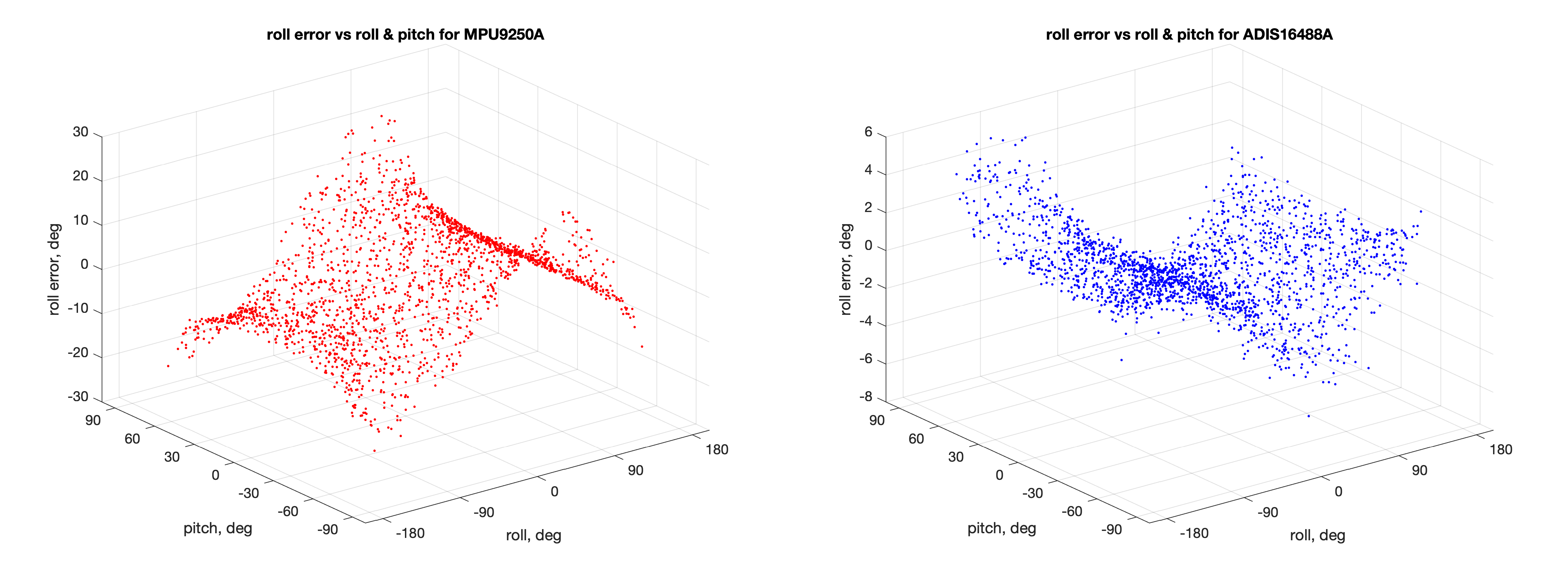
- This is how roll estimation errors depend on the roll and pitch values:
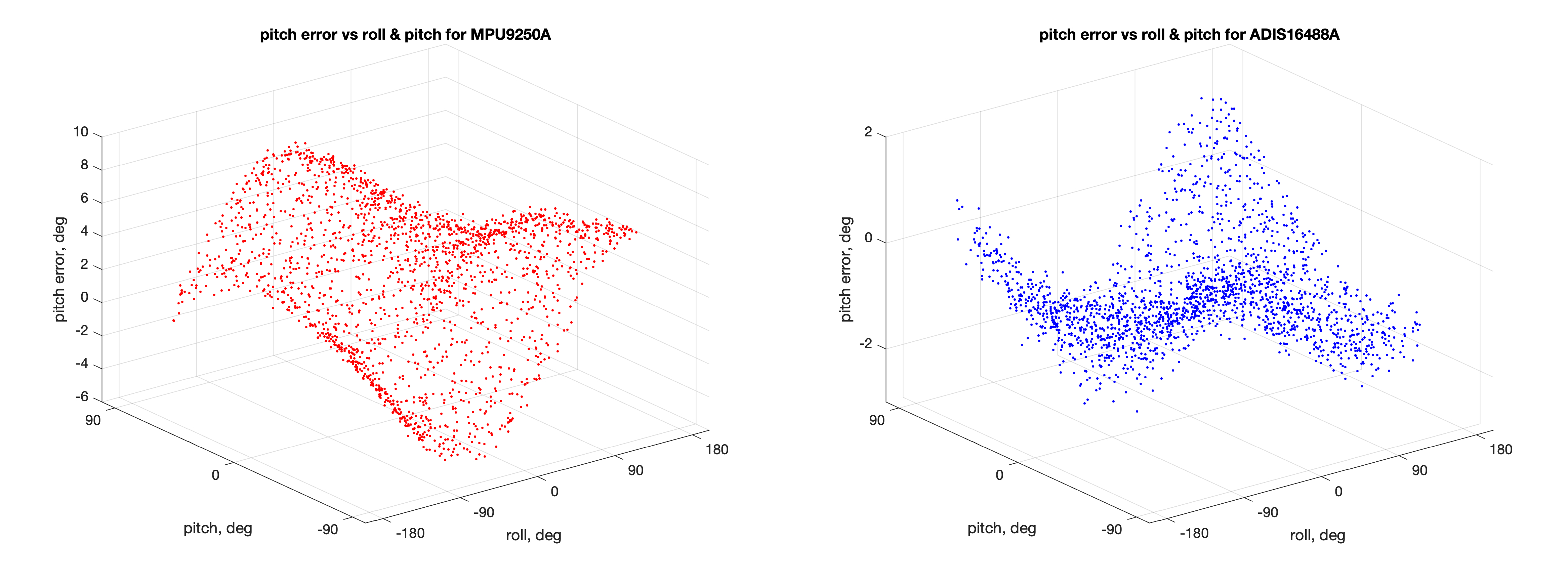
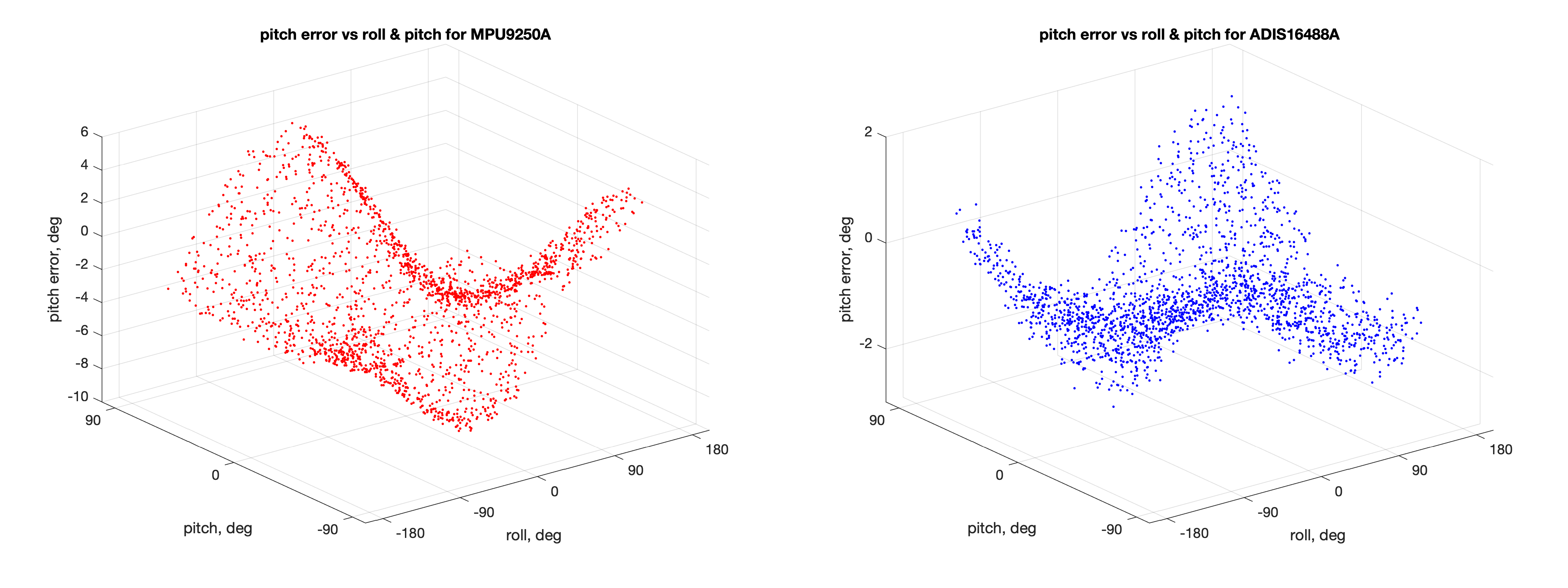
- How pitch estimation errors depend on roll and pitch values:
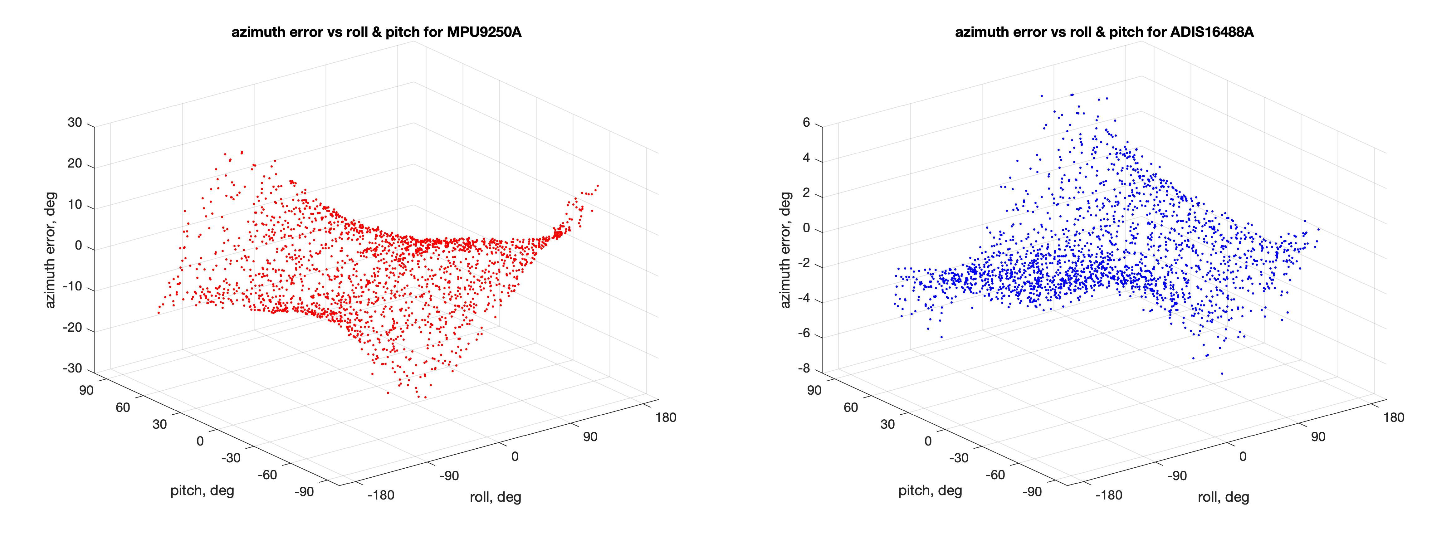
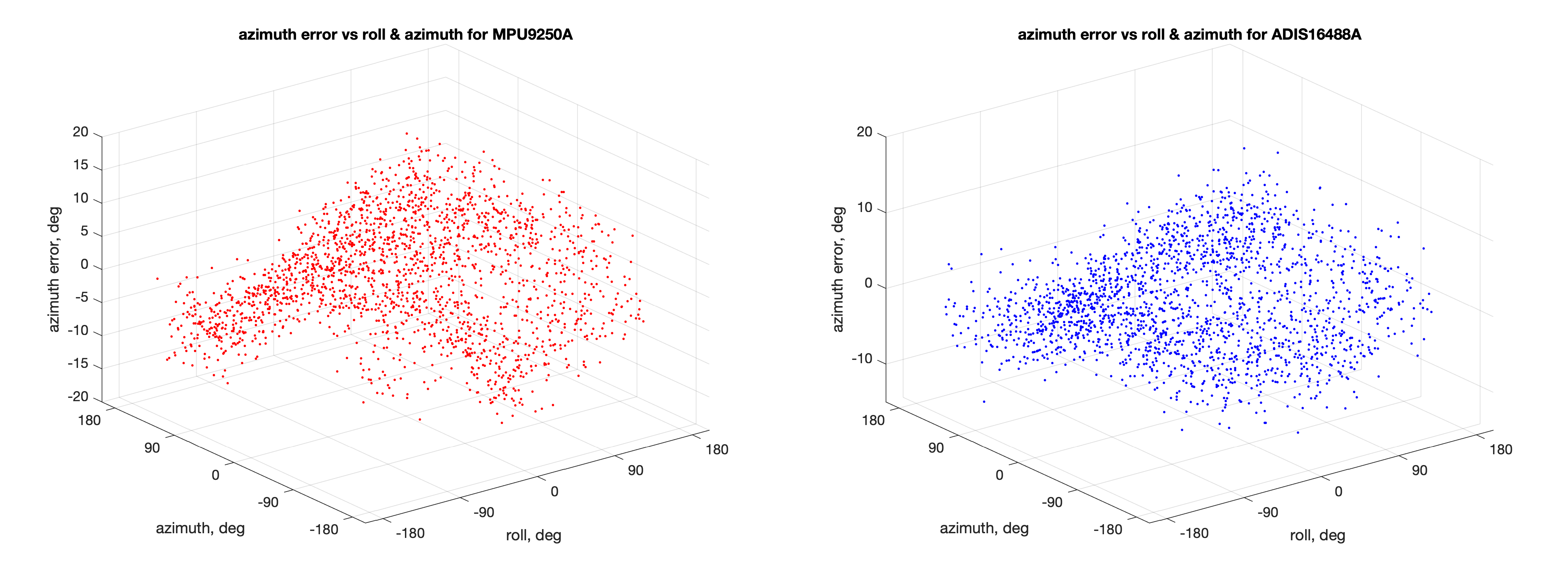
- How errors of magnetic azimuth estimation depend on roll and pitch angles:
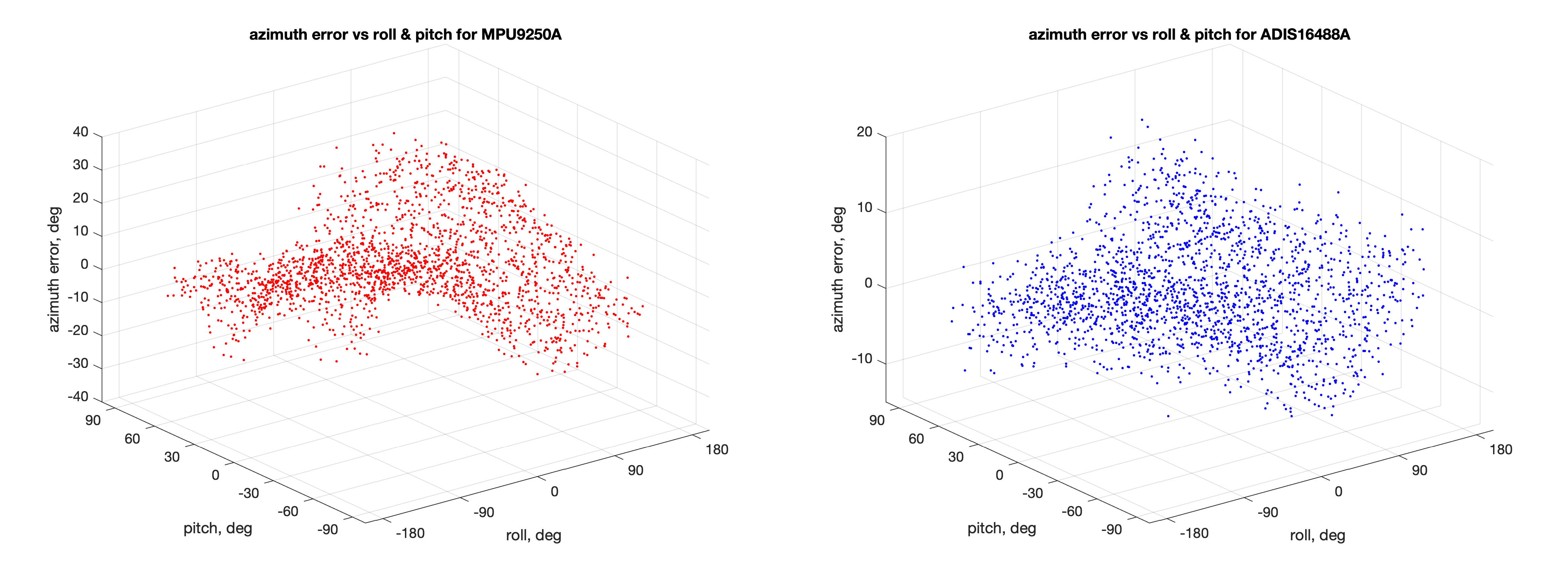
- How errors of magnetic azimuth estimation depend on roll and magnetic azimuth angles:

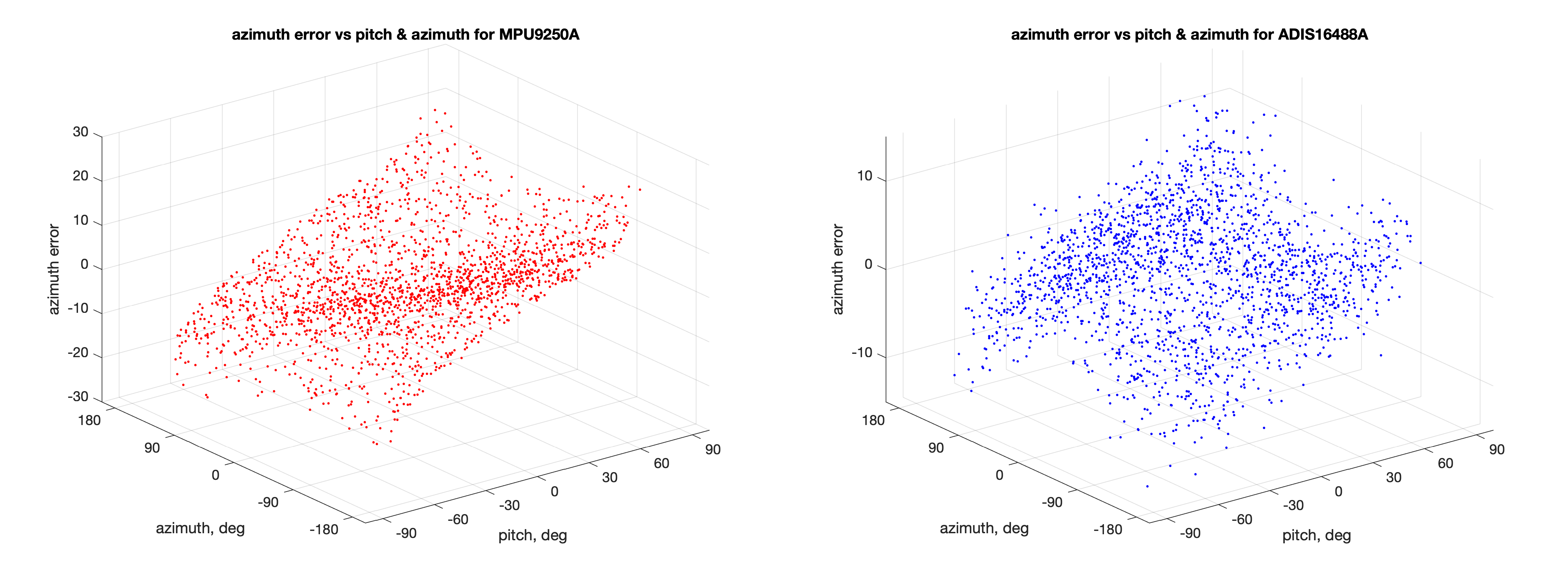
- How errors of magnetic azimuth estimation depend on pitch and magnetic azimuth angles:
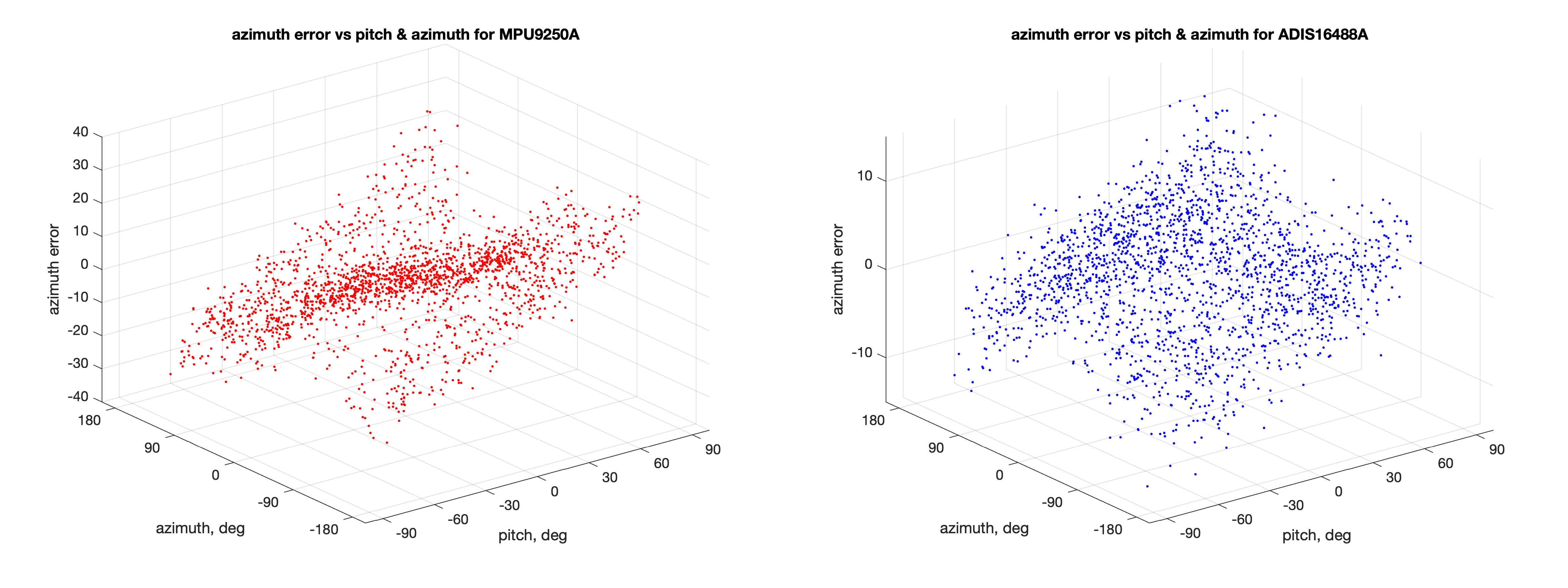
As you can see the magnitude of the errors increases when approaching the boundary of the angles range. Why?
Сonsider the figure below:

Suppose that we rotate the sensitivity axis Z
of the accelerometer so that the projection of gravity on this axis becomes smaller
. The value of the gravity projection plus the error of the accelerometer will give the range of possible measurement values (pink area). Angle estimation error increases
. So when gravity vector projection on the sensitivity axis decreases — constant accelerometer error begins to introduce a larger error into the angle estimate.
Now let's play with the input parameters to understand how the errors are defined:
Summary
- We have developed the Octave/MATLAB script that allows to estimate errors in the calculation of orientation angles from measurements of MEMS accelerometers and magnetometers.
- Errors in estimating orientation angles are the functions of all orientation angles. In this case the maximum values of errors are observed at the boundaries of the selected ranges of angles.
Spoiler - disclaimer:
- We don't recommend buying and using these sensors (they are quite old).
- We don't take into account the influence of non-linearity of measurements, the influence of vibration, instability. That's only the first approximation to the angles errors.
Literature
Authors
Moscow Power Engineering Institute, Dept. of Radio Systems


